How a Servo Motor Works
A servo motor is a type of electric motor that allows for precise control of angular position. Unlike a standard DC motor that spins freely, a servo motor can hold a specific position as long as a control signal is maintained. This is achieved through a closed-loop system with a few key components:
- DC Motor: The power source that rotates the output shaft.
- Gear Reduction: A series of gears that increase the torque and slow down the motor’s speed, allowing for more precise movement.
- Potentiometer: An internal variable resistor that acts as a sensor, measuring the current position of the output shaft.
- Control Circuit: The “brain” of the servo. It receives an external signal, compares it to the current position reported by the potentiometer, and then drives the motor in the correct direction until the two values match.
The servo holds its position by constantly making minor adjustments to counteract any external force trying to move the shaft.
Control Signal: Pulse Width Modulation (PWM)
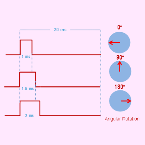
The Arduino controls the servo’s position using a special type of signal called Pulse Width Modulation (PWM). A servo motor expects to receive a pulse approximately every 20 milliseconds (a frequency of 50 Hz). The width of this pulse dictates the servo’s angle.
- A pulse width of 1 ms typically corresponds to the 0-degree position.
- A pulse width of 1.5 ms corresponds to the 90-degree (center) position.
- A pulse width of 2 ms corresponds to the 180-degree position.
Code : https://github.com/starlitelectronics/SensorArduinoESP32-ServoMotor.git